Before reading this entry I recommend you to read this introductory post to understand how video display works.
I’ve seen several attempts to make new video display hardware for older computers or processors, and many of them have taken the approach to focus on the hardware first. Although I think this is the realistic approach, it also has the problem that all the physical restrictions must be handled a priori, and the difficulties of such a task are so high that it can easily turn down all the enthusiasm someone could put in.
Tell me naive but I prefer to do the other way around, I prefer to design the video display from a software point of view and then see what are the restrictions that must be resolved to convert this design into real hardware. To start testing with emulation and once all the requirements are settled, the goal is set and the focus can be put in creating a hardware that implements that design in particular with no more fiddling required.
Having said that, still one must consider hardware restrictions, like memory available, memory access arbitration between the CPU and the graphics display, resolutions and number of colors that can be achieved, and more.
Fortunately there is a lot of knowledge about designing display devices, and how good or bad they worked for the computers and their programmers. This entry is about what I plan to do for Compy (CLC-88) and what are the options available for implementation. This design ideas are not for debating about them, but hopefully for receiving feedback about what things I may be missing for consideration.
Video memory
One of the problems that early designers needed to address was the access to video memory between the CPU and the display controller, and how to synchronize them. Let’s see the available options:
- System Memory: Computers like the C64, Atari800 and ZX Spectrum used part of the main memory as display memory and the CPU was halted while the video controller was accessing that memory. This was very convenient for the programmers because a simple memory read or write gave access to each pixel on the screen, but at the same time having more resolution and more colors required more system memory, so less memory was available for doing other stuff. That limited the graphics display to lower resolutions (Atari) or just a few colors (ZX), and a few hardware sprites or no sprites at all.
- Video RAM: Computers like the MSX based ones used a separate memory for video display. This has the advantage that there is no need to halt the CPU to access the video memory and any amounts of memory can be used for display, so high resolutions and a lot of colors were available, still leaving the system memory intact for other stuff. The downside is that memory access was made through a single port (IN/OUT) and this kind of access was not as easy as directly writing or reading from memory.
Now, there is some middle ground and this is the approach that Compy will take. This is having a separate Video RAM that is mappable into a System Memory region. This approach has the best of both worlds, there is plenty of memory available for display and everything else, the CPU or the video controller can access it without interfering each other and the programmer can use standard read/write methods to access that memory.
This method is already proven to be feasible, and it is the method used by the VBXE expansion for the Atari. Even using the same original 6502 processor and system, the video modes and features that are added by this board are very similar of what I want for Compy.
Implementation options
I already wrote about how the video interface could be implemented, now that I have a bit more knowledge I can see a much clearer about what is the way to go.
My plan is always start with emulation first to experiment with different designs without having to go through a full hardware implementation in between. Doing otherwise could led me to end trapped into hardware issues that I would have to learn how to handle, it would turn the design problem into a “learn electronic first” problem. With the emulator I can start testing the display capabilities with real code, to get a grasp of how the system would look for the coders. Having said that, the emulator for Compy is already started and I’ll start writing the video display code soon ™.
If everything hardware fails, at least I will end with an emulated machine that can be run on any system. I could boot a Raspberry Pi directly into Compy and start using it with my CRT. That’s the worst case scenario and I would be really happy with that.
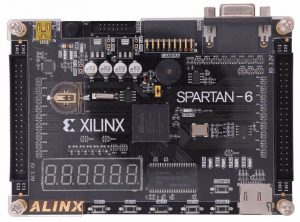
Enters FPGA
Now, if I could go further into the hardware realm I would take the FPGA route. For those who don’t know what FPGA is, imagine a silicon with a lot of “logic units” but they are not connected, so there is no logic implemented on it. A hardware programmer creates some logic on a computer and uploads the design to this silicon so the logic units get connected to implement that logic. As someone said, “schematics” for this kind of electronics is old school, now you just write your logic as code and the FPGA is configured to implement that logic.
Now, this may sound like uploading a software to a computer but it is not. One notorious difference is that the computer that we all programmers know works in sequential steps, meanwhile an FPGA works as a massive parallel device.
This is better understood with an example. Let’s think that we need to read two pins and make an AND operation between them. Using a computer this can be done in 5 steps: 1) read the first pin, 2) mask the bit, 3) read the second pin, 4) mask the bit, 5) perform the AND operation between both masked bits. Using an FPGA is just one step: connecting both pins to an AND gate. Now, if we want to process that result, in a classic computer that will require extra steps that will be added to the already 5 steps that we have, instead on a FPGA that will only be a “propagation” time to other logic units. Also, consider that the classic computer will never be able to read both pins at the same time unless they are mapped in the same byte, while an FPGA not only can read those two pins at the same time, but it is able to read a lot of inputs at the same time, that’s massive parallel.
With that in mind, a 50Mhz FPGA cannot be in any case compared to a 50Mhz microprocessor, they are just radically different on what they can do on each clock cycle.
Compy on FPGA
Using FPGA opens a lot of options, not only the video controller can be implemented on it, also the processors and everything in the digital domain can be put on it. One would not require to create a PCB to attach the 6502 and Z80, they will be just put into the FPGA and connected via code. This is nothing new, this is what projects like One Chip MSX and MIST Computer already have done. They already implement full computers on a single FPGA, and that is far more advanced of what Compy may need, it is enough proof that a small computer like Compy could be fully implemented in FPGA.
Thanks to the community, processors like the 6502 and Z80 are available as open source for FPGA, so they can be integrated without having to write the full code for them.
Now, FPGA solves the digital domain, but what about the analog domain? Again, there are many options, from boards that already include sound and video (VGA) outputs to add on cards that can be used from any digital domains. These cards usually includes some sort of DAC units to convert digital values to variable current values, required to drive audio and video. Even if they wouldn’t exist, it is easy to create a DAC with a resistor ladder, in fact that is what some VGA add ons use. There are some very cheap VGA adapters for 16 bit conversions (RGB 565 / 64k colors) but easily one can made a resitor ladder DAC with 8 or more bits per channel (16M colors and more)
FPGA as a processor
There is another interesting way of going the FPGA route. The logic part can be left to the already existing chips, but the new video chip doesn’t need to be implemented as a specialized logic circuit, the same emulation code can be run in a processor inside the FPGA. Yes, what can be implemented in the FPGA is the processor that runs the existing video processor code from the emulator!
This can be done adding a new processor inside the FPGA as we could do it with the CPU’s, or use a FPGA that already includes an ARM processor ready to be used. Yes, what a time to be alive!
It’s all about timing (again)
Now, this sound too good to be true and it is. There are some trade offs and here comes again our friend “the timing”.
Existing 8 bit computers can modify the display as it is being generated. With precise timing a program can change any register in the video controllers as they are drawing the screen. That’s how coders from the demo scene achieve displays that have been considered impossible to do with the hardware limitations.
To have something similar in Compy, the part that is driving the display should be run at a speed in sync with the CPU, and that should be something stable if programmers would like to use it. In any case, may be I’m going to far in the future, given that there are no programmers doing code for Compy, not even myself. But it is something to take into consideration to have a “real computer”.
The other alternative is just let the display controller draw the screen with only scanline synchronization methods. I think this is more feasible and stable than relying on timed changes in the middle of a scanline. Here Display List Interrupts and methods like WSYNC can be safely implemented and used by the programmers. The only drawback that I foresee is that using emulation this will inevitable add one frame of lag between the actual execution and the screen display, but for now I can live with that.